Post by aerofoto - HJG Admin on Dec 1, 2009 6:50:25 GMT
We're now getting much closer to being able to launch our new line of DC9 panels.
Firstly .... I need to extend our sincere thanks and appreciation to Stellan HILMERBY for allowing us to use, and to modify, his original DC9 panel/s .... "THANK YOU" Stellan !
Secondly .... I also need to extend our equally sincere thanks to my colleague George CARTY for the huge amount of work he's undertaken these past 12 months in order to successfully modify/improve Stellan's original panel/s for adaption to Nick BOTAMER's new DC9 models and FDE .... "THANK YOU" also George !
Unfortunately, I do also need to stress, that these new DC9 panels will be FS9/FS2004 compatible only.
Despite his very best efforts, George was unable to access the original Source Code/Logic for these. Without this essential data these panels can't, so easily, be made FSX compatible. In fact it's taken George well over a year to both improve and adapt these for use with our own aircraft models/FDE and using the data we could obtain. I realize this news will likely disappoint our FSX community and despite the fact our DC9 project is otherwise already FSX compatible, but, I also appeal to these folk to understand that we're powerless to do anything about this under the circumstances

This project has been one of the most, if not "THE MOST", complex panel production yet undertaken by HJG.
It's not been a particularly easy project either !
The fact we've been able to achieve what we've managed to achieve with these new DC9 panels is due entirely to George's skill and dedication !
What we're going to release soon, I believe, will be "THE VERY BEST" freeware DC9 panels currently available for FS9/FS2004.
Those already familiar with any of the original HILMERBY DC9 panel/s, or, previously modified versions of these, will find George's panel modifications represent significant improvements .... of course I state this in all due respect to both the original panel authors and those whom have previously endeavored to improve these in the past.
ANYWAY ....
Here's a few images and explanatory notes intended to introduce/present what we'll be soon offering ....
This's the new DC9 Main Panel .... with its much improved/clearer MAIN PANEL.BMP. This first image represents the Main Panel view that will apply to most of our DC9 series aircraft ....

This next image represents another variation of Main Panel which will be used mostly for the later model DC9 versions only .... or those aircraft with more advanced and higher engine thrust ratings in particular. The essential difference between both of these Main Panel views is the EPR THRUST LIMIT COMPUTER .... just to the left of the EPR and N1 guages and which is visible in the following image .... located just to the left of the EPR and N1 guages ....

The EPR LIMITS COMPUTER provides constantly updating digital information in relation to precisely that .... "maximum recommended engine EPR" .... and which should be observed for T/O, during climb, throughout the cruise, and during descent etc .... this data is calculated automatically on the basis of altitude and ambient/air temperature etc. This digital gauge replaces the similar older analogue vertical scale gauge which is visible in the first Main Panel image above. Our DC9 panels will also each feature engine instrumentation calibrated, as best as FS will permit, according to the known performance parameters of each aircraft/engine type and as has been the case for each of our other past aircraft/engine type panel productions.
Still on the subject of Main Panel details ....
The Fire Warning system .... located above the engine # 1 and engine # 2 EPR guages .... works "IN TEST MODE ONLY" (just like that in our B727 panels). These Fire Warning system lamps illuminate ....
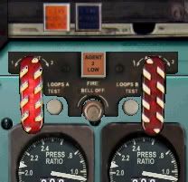
.... which in turn triggers the Fire Warning system bell and also then causes the red Main Panel Master Caution lamp to illuminate too ....

.... as well as resulting in an illuminated warning appearing on the Overhead Panel Annunciator. Both the Fire Warning system lamps and bell, along with both the Master Caution and Annunciator warning lamps too, must all be cancelled manually.
This's the DC9 Overhead Panel view .... similarly tidied up by George .... presented here showing most of its essential items already having been activated. This particular panel might, to some, look complex .... BUT I CAN ASSURE EVERYONE .... it's "NOT" all that difficult or hard to understand. If only folk take a few minutes to study the DC9 PANEL INSTALLATION & HANDLING NOTES information which will be provided upon the release of these panels then all should appear adequately/clearly explained and in simple/basic "STEP BY STEP" fashion .... just as I've endeavored to do in relation in the case of each of our other current panels for which I've written similar support notes ....
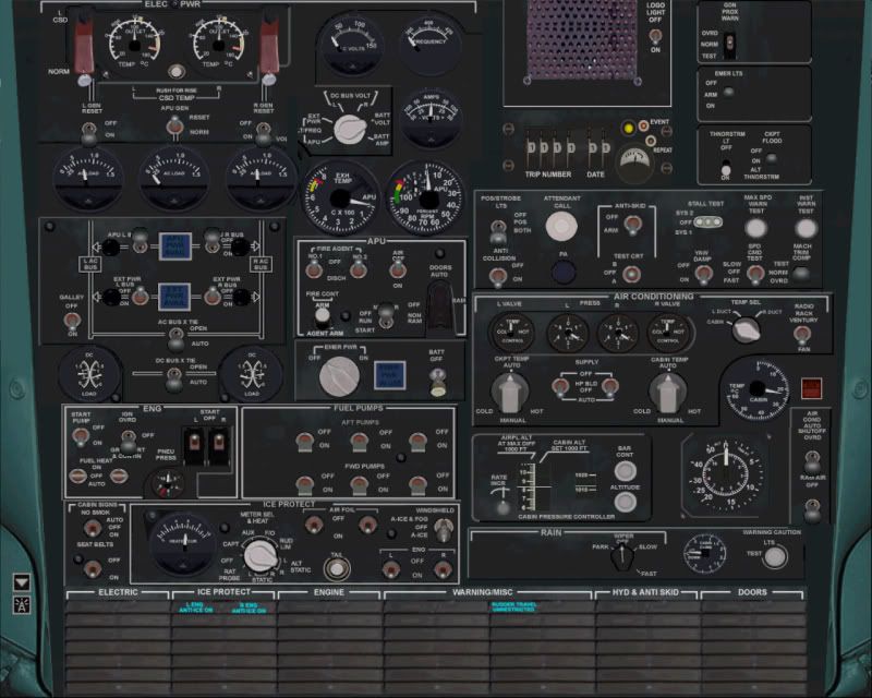
The upper left section of the Overhead Panel features mostly Electrical Bus switches. The bottom left section features Cabin Notices switches, Anti-Ice System switches, and switches for the Fuel Pump system. The center left section features Engine Startup switches, and switches and gauges relating to the APU system .... which is fully operable and must be used during engine startup procedures. The upper right section features mostly Lighting switches, and the GPWS warning test switch. The center right section features further Lighting related switches, Anti-Skid, Yaw Damper, and test switches for both Stall and Overspeed warning systems. The lower right section features the Air Conditioning and Pressurization system switches and scales, as well as the Annunciator warning lamp test button.
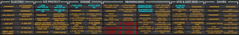
The comprehensive and fully functional Annunciator warning lamp system provides a multiplice of illuminated warnings/advisories, when necessary/triggered, relating to all aspects these panels and aircraft operations .... and as appears in the following image ....
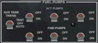
The Overhead Panel assigned to some of our DC9's will differ only in the inclusion of an AUXILIARY FUEL TANK switch .... located just to left of the 6 principal Fuel Pump system switches visible in both the full Overhead Panel view above .... and as is evident in this following close-up image showing the Overhead Panel Fuel Pump system ....
The following image features the Hydraulics system panel and related pressure gauges .... which are are located in the bottom right section of this sub panel view. This sub panel also features the Oil Pressure/Temp/Quantity gauges, Fuel Quantity/Reset button, Landing Gear lamps, Gear Door Position lamp, Slat/Flap lamp and Flap gauge, engine # 2 F/F gauge (the engine # 1 F/F gauge is located on the Main Panel), and the TAS gauge too ....
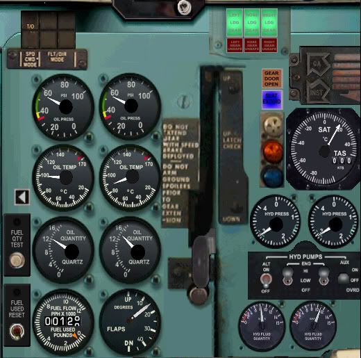
In particular the 2 center Hydraulics Pump switches, among the 4 switches visible in this image of the Hydraulics Panel, are absolutely "IMPERATIVE" ....
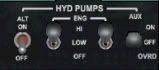
.... both of these switches must first be set to their fully up/"HI" positions (as depicted) before the aircrafts Slats/Flaps and Landing Gear can be extended/retracted.
Here's the Center Pedestal panel .... featuring all the usual devices one's accustomed to seek here .... such as Trim Setting, Thrust Levers, Engine Fuel Start/Cut-Off levers, and both Spoiler and Flap/Slat Levers .... BUT .... also featuring a black handled Fuel Cross-Feed system Lever (marked with a white "X") located to the left of the Flap lever, a yellow handled Rudder Power lever (marked with a black spot and white "R") located to the right of the Spoiler Lever, along with a Yellow Cabin Pressurization system lever/tab located near the bottom left of the Flap Lever track on this sub panel view .... each of these devices must be set prior to T/O. The 2 large white capped levers located at the very bottom right section of this sub panel view are the Engine Startup Fuel Cross Feed valves/levers which are absolutely "IMPERATIVE" during engine startup procedures .... both must be set to their fully "UP" position (as depicted) or the engines simply will not start. The Center Pedestal also features an Auto-Throttle system switch .... but .... this particular AT .... intentionally .... isn't used to maintain thrust for a constant speed during climb, cruise, or descent. Thrust during these flight regimes must be set and adjusted manually in order to maintain speed. This particular AT system is used, if at all, only to maintain a specific/constant V-REF (calculated according to aircraft weight and which is then used for setting the speed bugs on the ASI) during approaches to landing ....
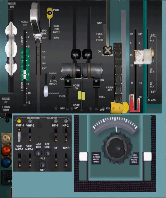
The Weather Radar panel is a completely new feature for these DC9 panels. It's identical to that featured within each of our current B707/720, B727, CV880/CV990, and DC8 panels. This Weather Radar is dependent on any freeware version of FSUIPC subsequent to V3.50 in order for it to be able function. This sub panel view also features the ADF Radios ....
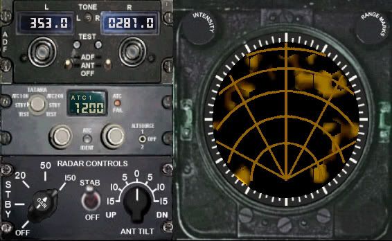
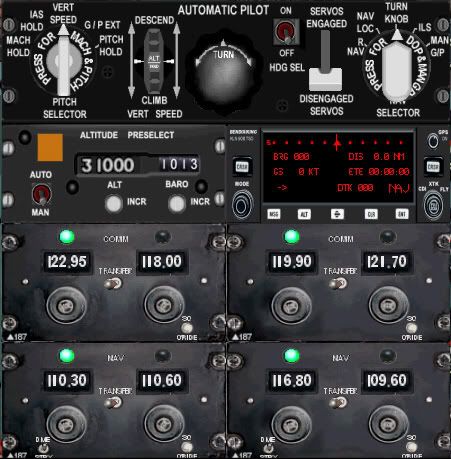
And here's the Auto-Pilot Panel which .... which is fundamentally similar to that featured within each of our current CV880/CV990 and DC8 panels, but, which also comes with a couple of additional functions too .... among which are included an automatic preselected Altutide Capture function. This sub panel view also features the Radio Stack which includes both Navigation and Communications systems ....
And .... last but by no means least of all .... I also need to express our sincere thanks to my colleague Nick BOTAMER for our great new DC9 project .... and also to my colleague Mike MONCE for his invaluable FDE expertise (George has also played a major role here in terms of FDE/Panel compatibility) in trying to replicate credible DC9 performance throughout our entire range of these aircraft.... "THANKS ALSO" guys !
Aviation is a relatively sophisticated business .... I think most will agree.
What we've got here, per this new DC9 panel series, I feel, tends to reflect this .... to some extent .... BUT THERE AGAIN .... not to such an extent that folk will have difficulty using these panels. At least not if they first take the time necessary in order to familiarize themselves with all the support notes that will be provided when these panels are eventually released.
Like applies to most things in life, both aviation and non-aviation alike, a little study is essential to be able to understand, use, and in particular enjoy this forthcomming new range of great DC9 panels .... of course !
Additional information regarding our new DC9 panel range can also be viewed here ....
tonymadgehjg.proboards.com/index.cgi?board=previews&action=display&thread=2873
Mark C
AKL/NZ
Firstly .... I need to extend our sincere thanks and appreciation to Stellan HILMERBY for allowing us to use, and to modify, his original DC9 panel/s .... "THANK YOU" Stellan !

Secondly .... I also need to extend our equally sincere thanks to my colleague George CARTY for the huge amount of work he's undertaken these past 12 months in order to successfully modify/improve Stellan's original panel/s for adaption to Nick BOTAMER's new DC9 models and FDE .... "THANK YOU" also George !
Unfortunately, I do also need to stress, that these new DC9 panels will be FS9/FS2004 compatible only.
Despite his very best efforts, George was unable to access the original Source Code/Logic for these. Without this essential data these panels can't, so easily, be made FSX compatible. In fact it's taken George well over a year to both improve and adapt these for use with our own aircraft models/FDE and using the data we could obtain. I realize this news will likely disappoint our FSX community and despite the fact our DC9 project is otherwise already FSX compatible, but, I also appeal to these folk to understand that we're powerless to do anything about this under the circumstances


This project has been one of the most, if not "THE MOST", complex panel production yet undertaken by HJG.
It's not been a particularly easy project either !

The fact we've been able to achieve what we've managed to achieve with these new DC9 panels is due entirely to George's skill and dedication !
What we're going to release soon, I believe, will be "THE VERY BEST" freeware DC9 panels currently available for FS9/FS2004.
Those already familiar with any of the original HILMERBY DC9 panel/s, or, previously modified versions of these, will find George's panel modifications represent significant improvements .... of course I state this in all due respect to both the original panel authors and those whom have previously endeavored to improve these in the past.
ANYWAY ....

Here's a few images and explanatory notes intended to introduce/present what we'll be soon offering ....
This's the new DC9 Main Panel .... with its much improved/clearer MAIN PANEL.BMP. This first image represents the Main Panel view that will apply to most of our DC9 series aircraft ....
This next image represents another variation of Main Panel which will be used mostly for the later model DC9 versions only .... or those aircraft with more advanced and higher engine thrust ratings in particular. The essential difference between both of these Main Panel views is the EPR THRUST LIMIT COMPUTER .... just to the left of the EPR and N1 guages and which is visible in the following image .... located just to the left of the EPR and N1 guages ....
The EPR LIMITS COMPUTER provides constantly updating digital information in relation to precisely that .... "maximum recommended engine EPR" .... and which should be observed for T/O, during climb, throughout the cruise, and during descent etc .... this data is calculated automatically on the basis of altitude and ambient/air temperature etc. This digital gauge replaces the similar older analogue vertical scale gauge which is visible in the first Main Panel image above. Our DC9 panels will also each feature engine instrumentation calibrated, as best as FS will permit, according to the known performance parameters of each aircraft/engine type and as has been the case for each of our other past aircraft/engine type panel productions.
Still on the subject of Main Panel details ....
The Fire Warning system .... located above the engine # 1 and engine # 2 EPR guages .... works "IN TEST MODE ONLY" (just like that in our B727 panels). These Fire Warning system lamps illuminate ....
.... which in turn triggers the Fire Warning system bell and also then causes the red Main Panel Master Caution lamp to illuminate too ....
.... as well as resulting in an illuminated warning appearing on the Overhead Panel Annunciator. Both the Fire Warning system lamps and bell, along with both the Master Caution and Annunciator warning lamps too, must all be cancelled manually.
This's the DC9 Overhead Panel view .... similarly tidied up by George .... presented here showing most of its essential items already having been activated. This particular panel might, to some, look complex .... BUT I CAN ASSURE EVERYONE .... it's "NOT" all that difficult or hard to understand. If only folk take a few minutes to study the DC9 PANEL INSTALLATION & HANDLING NOTES information which will be provided upon the release of these panels then all should appear adequately/clearly explained and in simple/basic "STEP BY STEP" fashion .... just as I've endeavored to do in relation in the case of each of our other current panels for which I've written similar support notes ....
The upper left section of the Overhead Panel features mostly Electrical Bus switches. The bottom left section features Cabin Notices switches, Anti-Ice System switches, and switches for the Fuel Pump system. The center left section features Engine Startup switches, and switches and gauges relating to the APU system .... which is fully operable and must be used during engine startup procedures. The upper right section features mostly Lighting switches, and the GPWS warning test switch. The center right section features further Lighting related switches, Anti-Skid, Yaw Damper, and test switches for both Stall and Overspeed warning systems. The lower right section features the Air Conditioning and Pressurization system switches and scales, as well as the Annunciator warning lamp test button.
The comprehensive and fully functional Annunciator warning lamp system provides a multiplice of illuminated warnings/advisories, when necessary/triggered, relating to all aspects these panels and aircraft operations .... and as appears in the following image ....
The Overhead Panel assigned to some of our DC9's will differ only in the inclusion of an AUXILIARY FUEL TANK switch .... located just to left of the 6 principal Fuel Pump system switches visible in both the full Overhead Panel view above .... and as is evident in this following close-up image showing the Overhead Panel Fuel Pump system ....
The following image features the Hydraulics system panel and related pressure gauges .... which are are located in the bottom right section of this sub panel view. This sub panel also features the Oil Pressure/Temp/Quantity gauges, Fuel Quantity/Reset button, Landing Gear lamps, Gear Door Position lamp, Slat/Flap lamp and Flap gauge, engine # 2 F/F gauge (the engine # 1 F/F gauge is located on the Main Panel), and the TAS gauge too ....
In particular the 2 center Hydraulics Pump switches, among the 4 switches visible in this image of the Hydraulics Panel, are absolutely "IMPERATIVE" ....
.... both of these switches must first be set to their fully up/"HI" positions (as depicted) before the aircrafts Slats/Flaps and Landing Gear can be extended/retracted.
Here's the Center Pedestal panel .... featuring all the usual devices one's accustomed to seek here .... such as Trim Setting, Thrust Levers, Engine Fuel Start/Cut-Off levers, and both Spoiler and Flap/Slat Levers .... BUT .... also featuring a black handled Fuel Cross-Feed system Lever (marked with a white "X") located to the left of the Flap lever, a yellow handled Rudder Power lever (marked with a black spot and white "R") located to the right of the Spoiler Lever, along with a Yellow Cabin Pressurization system lever/tab located near the bottom left of the Flap Lever track on this sub panel view .... each of these devices must be set prior to T/O. The 2 large white capped levers located at the very bottom right section of this sub panel view are the Engine Startup Fuel Cross Feed valves/levers which are absolutely "IMPERATIVE" during engine startup procedures .... both must be set to their fully "UP" position (as depicted) or the engines simply will not start. The Center Pedestal also features an Auto-Throttle system switch .... but .... this particular AT .... intentionally .... isn't used to maintain thrust for a constant speed during climb, cruise, or descent. Thrust during these flight regimes must be set and adjusted manually in order to maintain speed. This particular AT system is used, if at all, only to maintain a specific/constant V-REF (calculated according to aircraft weight and which is then used for setting the speed bugs on the ASI) during approaches to landing ....
The Weather Radar panel is a completely new feature for these DC9 panels. It's identical to that featured within each of our current B707/720, B727, CV880/CV990, and DC8 panels. This Weather Radar is dependent on any freeware version of FSUIPC subsequent to V3.50 in order for it to be able function. This sub panel view also features the ADF Radios ....
And here's the Auto-Pilot Panel which .... which is fundamentally similar to that featured within each of our current CV880/CV990 and DC8 panels, but, which also comes with a couple of additional functions too .... among which are included an automatic preselected Altutide Capture function. This sub panel view also features the Radio Stack which includes both Navigation and Communications systems ....
And .... last but by no means least of all .... I also need to express our sincere thanks to my colleague Nick BOTAMER for our great new DC9 project .... and also to my colleague Mike MONCE for his invaluable FDE expertise (George has also played a major role here in terms of FDE/Panel compatibility) in trying to replicate credible DC9 performance throughout our entire range of these aircraft.... "THANKS ALSO" guys !
Aviation is a relatively sophisticated business .... I think most will agree.
What we've got here, per this new DC9 panel series, I feel, tends to reflect this .... to some extent .... BUT THERE AGAIN .... not to such an extent that folk will have difficulty using these panels. At least not if they first take the time necessary in order to familiarize themselves with all the support notes that will be provided when these panels are eventually released.
Like applies to most things in life, both aviation and non-aviation alike, a little study is essential to be able to understand, use, and in particular enjoy this forthcomming new range of great DC9 panels .... of course !
Additional information regarding our new DC9 panel range can also be viewed here ....
tonymadgehjg.proboards.com/index.cgi?board=previews&action=display&thread=2873
Mark C
AKL/NZ