|
|
Post by Benoit - HJG on Oct 2, 2016 21:13:13 GMT
Previews of Pratt & Whitney JT3C turbojet engine sounds for DC-8-11 / -12 series.
The last of the previews for our upcoming DC-8 soundpacks upgrades.
Benoit
Flightdeck environment views
External views
|
|
|
|
Post by aerofoto - HJG Admin on Oct 2, 2016 21:56:03 GMT
"AND BENOIT DOES IT AGAIN" .... an only Benoit can  Folks .... this's "PART 4 (B)" of HJG's new DC-8 audio upgrade project. This being the 2nd part of Benoit's turbojet series soundpacks for our early DC-8 series simulations bringing the voice of the DC-8's back to life .... this presentation replicating the water/methanol injected P&W JT3C turbojet for DC-8-11/12 aircraft specifically. This new new soundpack .... like each of the others recently previewed by Benoit also .... is, once again, customised for use with our new/current V5.4 DC-8 FDE and will replace our current turbojet audio. Separate JT3C and JT4A soundpacks "ARE" necessary due to the tonal differences between both engine types .... as well as the AIR file thrust curving differences within the FDE supplied provided within these DC-8 simulatios and upo whic these sondpacks are all based. The P&W JT3C turbojet engine .... being water/methanol injected (unlike the JT4A turbojet) was the "L-O-U-D-est" and "D-I-R-T-Y-est" of the P&W civil turbojet engine series ....   Once again .... this early turbojet engine version also exhibited "different" sound characteristics than the JT4A turbojet and both RR CONWAY JT3D series fanjet engines which followed it into service .... right down to their startup howl (a unique audio characterisic of early DC-8 SERIES aircraft and up to the SUPER 61) and which is due, in part, to the different starters and nacelle shape of these engines. I understand there will be a "2nd version" of this particular JT3C turbojet soundpack also .... especially for DC-8 SHIP ONE 1958 .... 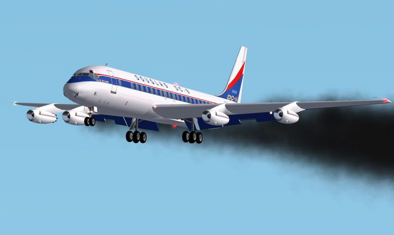  .... the engines of which were not equipped with thrust reversers. "W-O-N-D-E-R-F-U-L WORK " Benoit .... and "THANKS" once again Mark C AKL/NZ |
|
|
|
Post by Klaus Hullermann on Oct 3, 2016 8:09:36 GMT
You're so right Mark: Benoit did a fantastic job again and I can't wait to hear/watch the preview-video of the soundpack(s) for the DC-8 Ship One.
I have one question 'roaming' through my head for some years now: Why do the Turbofan-JT3 engines of the DC-8 look so different when you compare them with the Turbofan-JT3 of the Boeing 707?
Can you 'enlighten' me (and the other forum-members/-lurkers), please?
Klaus
|
|
|
|
Post by aerofoto - HJG Admin on Oct 3, 2016 19:28:20 GMT
I don't think Benoit's planning any audio-visual of SHIP ONE soundpasck (probably not necessary since the only difference between it, and the DC8-11/12 version JT3C turbojet soundpack is the absence of reverse thrust) .... but .... we'll leave that up to him of course As far as you engine question is concerned .... I'm not sure .... BUT .... suspect aerodynamics might possibly play a part other than engineering of internal parts of the engine to accomodate the various plumbing and wire harness configurations as designed into both aircraft types (since the nacelle is essentially a shell around the engine itself) .... I suppose ....  ? There's also minor differences between the nacelle shape and intake diameter of the JT3C, JT4A, and RR CONWAY engines on DC-8's too .... but .... given the age/geneology of our 3D DC-8 models (admittedly) these features/differences, in most instances, aren't so obviously defined. Mark C AKL/NZ |
|
|
|
Post by Klaus Hullermann on Oct 4, 2016 5:42:33 GMT
Thanks Mark for the reply and again I have learned something new about those great Jetliners you guys are offering.
Klaus
|
|
|
|
Post by Herman on Oct 4, 2016 16:25:02 GMT
In addition to Mark's explanation above the two major differences that I notice are, and by the way the JT3C engine is not a turbofan but is a turbojet engine. 1. the engine pylons on the 707 are some what different in as much that they have air intakes at the front of the pylon as shown in these images. The DC-8 uses air intakes (scoops) in the front fuselage nose cone.   2. The 707 uses a somewhat different approach to the reverse thrust mechanisms of the DC-8. In the DC-8 they are know as retaining rings and are used as thrust reversers. This means that the actual engine in the 707 is located further to the front of the nacells thus making the engine intake nose cone more visible.   Herman |
|
|
|
Post by Nathan Ford - HJG on Oct 4, 2016 17:39:56 GMT
The difference in the pylon shapes where due to the "turbo compressors", used for the pressurisation on the 707. As they had three turbo compressors, only engines 2,3 and 4 had the bulbous pylon. Engine 1, being turbo compressor free had a nice sleek shape to it.
I'm not sure where the turbo compressors where fitted to the DC-8, but I always assumed that the intake under nacelle was used for it.
Cheers,
Nathan
|
|
|
|
Post by aerofoto - HJG Admin on Oct 4, 2016 18:35:42 GMT
Although it may not be so visisble/obvious in some of the following images, but, the details "ARE" there .... AA B707-320B's and C's actually featured 2 turbo-compressors only (though this was standard among the B707-120/B, 138/B, -220, and B720/B) and which resulted in the 2 outboard engine pylons on these aircraft being identical, as well as the 2 inboard engine pylons on these aircraft being identical (but different from the other 2) as opposed to 3 turbo-compre4ssors which was common place virtually all other B707-320B's/C's .... 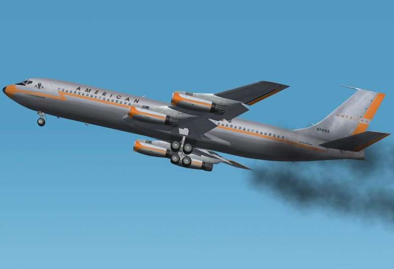     Of course the AA B707-320B's and C's eventually went on to fly with other operators afterward, so, this twin turbo-compressor configuration is something we/HJG need to be vigillant in rgard to whenever addressing B707-320B/C repaints .... especially in respect of aircraft that were former AA originals and since we "DO" have the correct/necessary 3D model configurations. George also took this into consideration within each of his "AA specific" B707-320B/C panels too .... which feature this unique twin turbo-comprerssor configuration on their F/E panels It's "small details" like this/these (which probably aren't commonly known) that tend to stand the HJG product/s aside from that of the opposition  Mark C AKL/NZ |
|
|
|
Post by Klaus Hullermann on Oct 5, 2016 4:45:27 GMT
Thanks Herman for correcting me. I know that the JT3C is a Turbojet-engine, but somehow my brain wanted me to write 'Turbofan' instead of the correct 'Turbojet'. Also I like the picture-explanation of the differences between the engines of the 707 and DC-8. Thanks Herman and Mark! I like the fact/love for those details that HJG offers 707-panels that adresses the AA-configuration of the Turbocompressors. As far as I know, no payware 707-version has this love for details. HJG ROCKS!!!  Klaus |
|
|
|
Post by Herman on Oct 5, 2016 6:04:10 GMT
Yes....Klaus....I also need to make a correction.
Do not know how I came up with '' retaining rings''. Should be ''Ejectors''.
Herman
|
|
|
|
Post by aerofoto - HJG Admin on Oct 5, 2016 6:15:58 GMT
Typically referred to as "EJECTORS" .... but also .... sometimes referred to as "T-RINGS" or "TRANSLATION RINGS" and which might account for your confusion Herman The turbojet powered B707's and B720's never had these though .... featuring just the "DAISEY PETAL" shaped exhaust end and an internal (inside the nacelle) thrust reverser mechanism. Mark C AKL/NZ |
|
|
|
Post by Herman on Oct 5, 2016 14:33:52 GMT
YES Mark, I think you are right about that. It appears that I only got the "rings" part right. Actually, to me, neither "Translation Rings" or "T-Rings or "Ejectors " makes much sense to me. Buckets or Clam Shells would be a more suitable name. From what I recall reading, this Douglas design had two functions, one, it did reduce noise somewhat, but their main purpose was to provide a means of thrust reversing. Herman |
|
|
|
Post by aerofoto - HJG Admin on Oct 5, 2016 18:29:02 GMT
"PRECISELY" .... thier thrust reverse functionality worked quite well, but, their success as a means of noise supression was "debateable".
For the new or uninitiated .... these Ejectors/Translation Rings/T-Rings "ARE" represented in each of the HJG DC-8-11/12, -20/-20F, -30/-30F, and -40/-40F 3D models (SHIP ONE 1958 wasn't equipped with these devices) .... and are extended/retracted using the pair of "EJECTOR" switches located within the top left of the O/H sub panel on our DC-8-10/-20/-30/and -40 panels, or, use keyboards commands "SHIFT + W". Enploy these devices within the flaqp speed range during T/O and landing only.
Mark C
AKL/NZ
|
|


 ?
?


